

12 - Component Rating Tester (for Audio Circuits) [ongoing...]

2024 12 04
Background - Why do I want to make this?
While shopping for amp heads, I went down a modding rabbit hole and people modding the tone-shaping circuitry in their amps with different value components (specifically resistors and capacitors). All this, was simply to change the frequency of the high-pass or low-pass filtering - because that’s all that these combinations of parts do. For example, a capacitor before a split to [1] resistor to ground and [2] main output, will result in the following high pass filter. Image below from LabCenter.com.
However, these Youtube modders changed component values based on what people in fora (forums) told them (examples: 1, 2, 3, 4), or what they heard around the very reliable audiophile watercooler. This serves no purpose other than change for the sake of speculative change, and all without testing. They never test, but always rely on what memory they had of their sound before they changed tubes, changed resistor, changed cables… So, to test, you’d ideally model the circuit in a program to simulate it (too advanced for me and this purpose) or calculate the filtering manually (too “on paper” for my taste), but what if you could just quick swap different components ratings to hear component changes live, in the same test/listening sitting, without soldering 12 times and possibly preserving solder pads on circuit boards
Why not just get a potentiometer?
I purposefully didn’t want a variable resistor/capacitor as the linearity and logarithmic(ness?) of it is variable (pun very much intended), it’s impossible to recall exactly the same position on the dial, and [1] I wanted reliability across components and their tolerances and [2] ability to recall an exact rating instead of fiddling around with a potentiometer and a scope until I got the right resistance/capacitance, and only then being able to check how that rating would sound. That, and variable resistors are, relatively speaking, far more expensive than regular, even “pro-audio”-grade, capacitors as the ones I ordered.
Explaining my reasoning for component choices:
I chose thin film resistors for their cost:performance and apparent self low noise (Source: EETimes), because I specifically need the field recording mics on which I will test this to have low self noise.

And, I got (mainly) metalized polypropylene capacitors because they have plently of benefits that are important in audio (Source: ElectroTechnik)

Before I go fiddling with >400Volt circuitry in an amp…
I am not yet comfortable inside an amp… mainly because I don’t have one anymore 😂
So, this tester will be trialed on my super sensitive DIY field recording mic, the EMR 5024 - I will try to tune its high pass and low pass filtering. I will also further explore why I got vastly superior THD with merely changing the capacitor rating (see update “2024 05 02” on that blog post).
Further on electrical safety:
While the capacitors and resistors chosen ARE rated for relatively high current and could be used in an amp, the Lorlin DS-1 (1-pole 12-position Rotating Switch) I chose for this is rated for a max of 5 Amps at 300V, and the contact probe solution that I will custom-make uses a connector with a max rating of 2 Amps at 50 VDC. It might be fine for most parts of a tube amp in the tone shaping section, but I’m still learning, so best not risk frizzing up my hair more than it already is. See homepage for proof/poof of hair.
Parts List
I tried to choose an as wide a range as possible of resistors and capacitors, that are of useful values and would affect signals inside our audible range.
12x Capacitors: 33 pF, 100 pF, 220 pF, 470 pF, 1 nF, 2.2 nF, 4.7 nF, 10 nF, 22 nF, 47 nF, 100 nF, 470 nF
12x Resistors: 470 ohms, 1 kΩ, 2.2 kΩ, 4.7 kΩ, 10 kΩ, 22 kΩ, 33 kΩ, 47 kΩ, 100 kΩ, 220 kΩ, 470 kΩ, 1 MΩ
Metal chassis
1-pole, 12-position Rotating Switch (this Lorlin DS-1 is super cool, it allows limiting how many positions you have and comes in surface-mount or solder joint versions)
Either two crockodile clip cables for each polarity, or install a plug/play-able port like I did (though I just did it for fun)
B.O.M.:
I happen to use Reichelt.de for these kinds of purchases, and have made a public BOM for each version. (prices/availability from time of writing)
the Resistor version project HERE (Tot €16.38)
the Capacitor version of the project HERE (Tot €19.12)
The wiring is dead simple
I’d provide a Circuitlab diagram as in my other posts, but I was having difficulties with Circuitlab, in that it only has a 2-pole switch… and this is a 12-pole selector.
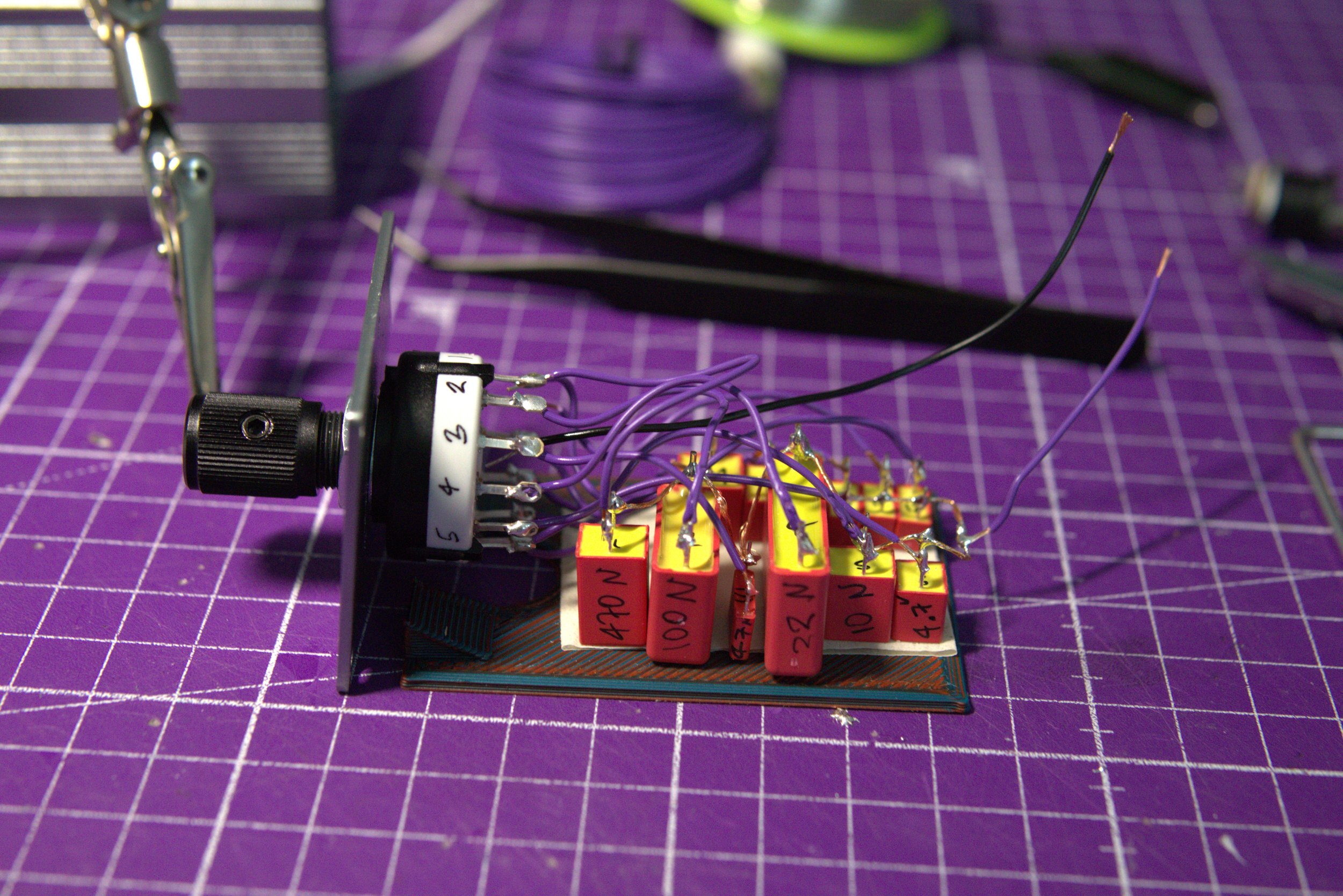
Below you will find images of the assembly.
The capacitor version is a little more involved as I needed to make a base for it, as the caps I selected were quite tall. So, they had to be laid flat and then slid into the (80 x 50 x 40 mm) chassis internal cutout for just such a base plate. The 3D file for the base plate is available on Thingiverse or Printables.
Note: I recommend you use a prototype board that fits into the chassis instead of this free standing version. I didn’t have any so made do with the caps on this DIY base plate.

Current flow is irrelevant
Since both the resistors and capacitors used are NON POLAR, it doesn’t matter what orientation you use and there isn’t a positive/negative to worry about.
The order of components for mine is the following: From the negative terminal of the DC port ground pin, to the resistors/capacitors (one pole of each is on a shared rail), then each component goes to their corresponding Nr on the 12-pole selector, and then center pin from the selector to the “positive” pin on the DC port.


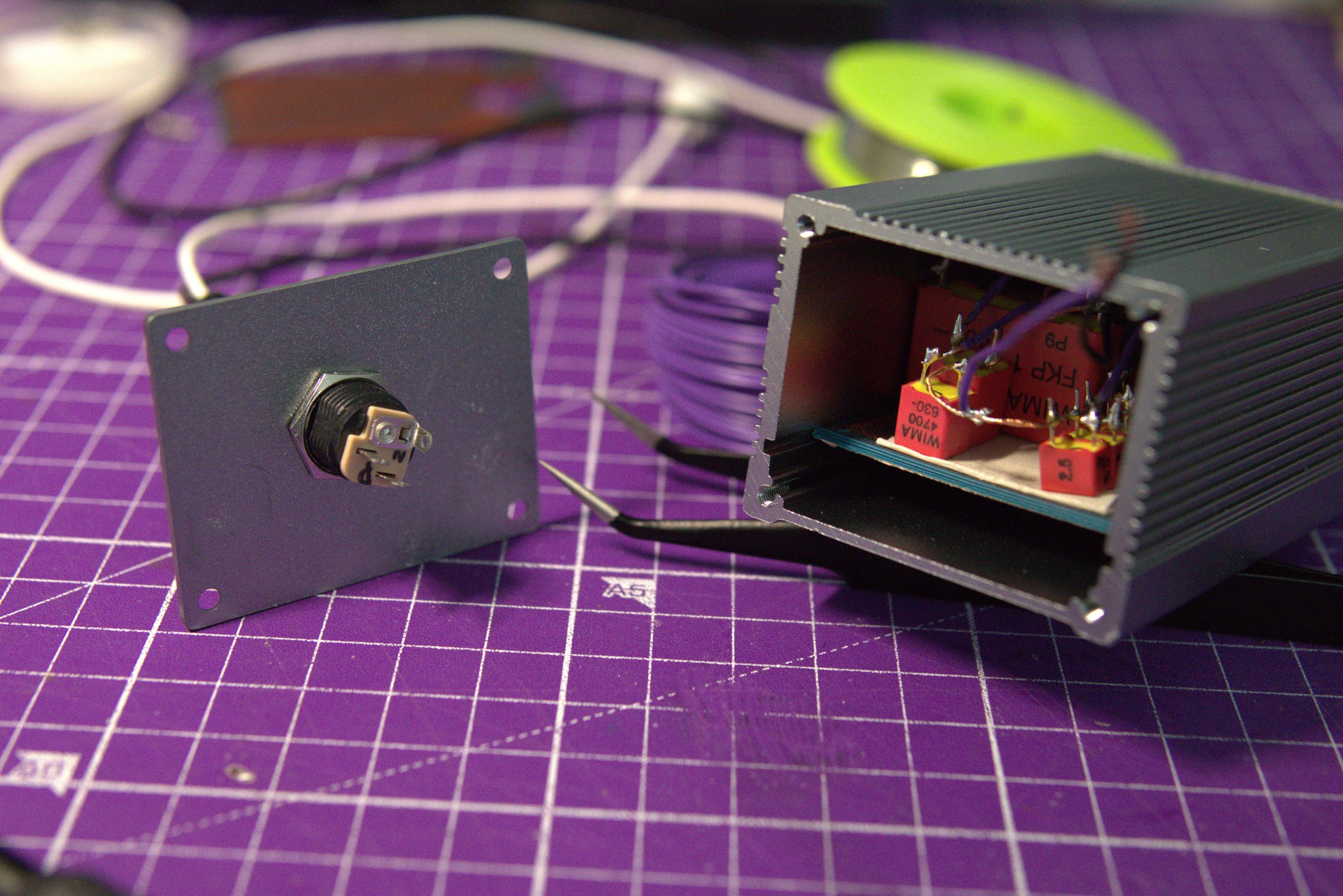
I then made a DC barrel connector to dual crocodile clip cable, which I could use to easily splice into circuits.
For example, I could use both of these, represented as the variable resistor and variable capacitor, in my DIY microphones.
Below is a diagram of an XLR’s pin outs with these Variable Resistor/Capacitor Units, and the rest of the microphone is… you guessed it, the microphone symbol. Good job!!
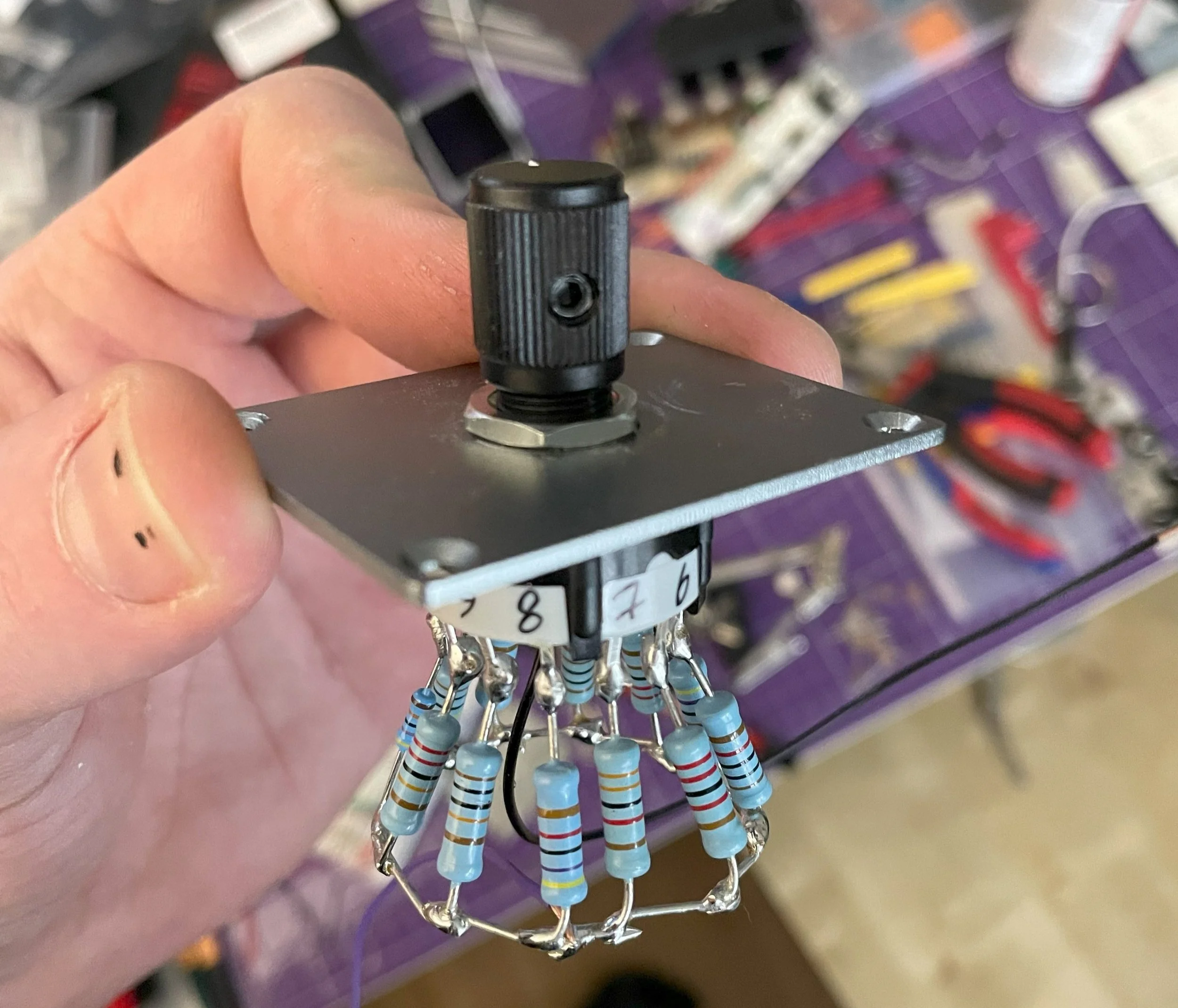
The resistor version was even easier
Here you can just solder the tiny components, as are most resistors, straight to the corresponding selector terminal. I’d suggest double checking the values with a multimeter and organizing them on a piece of tape how you want them installed on the selector from positions 1 to 12. I’ll never memorize resistor colors, so I like to double check and make sure they don’t roll all over the place.
Shared Rail
In this resistor version you can really see the shared rail, to simplify wiring. This shared rail could be seen as the input from the outside, and the output is the center pin of the selector.
The left is straight from the 12-pole selector spec sheet. Whereas the very crude diagram is what a backplate could’ve looked like on the box, where it shows where the selector knob is positioned, because right now there is no indication unless you measure it or click back to position 1, and then count up. This isn’t ideal, but until I can either 3d print or just scribble the values on the unit, I’m not too bothered counting the position of the value.

2025 07 02 UPDATE
I finally got a chance to build along to a JHS video and in building along, found an issue with my ceramic caps in my Arduino kit… and that ceramic caps are really not ideal for audio application; how was I supposed to know!?
An excellent opportunity for my component tester, and I’m beyond ecstatic that I built this thing. The ability to fine tune the cap for the application is game changing, instead of theorizing using formulas in which I’m not yet confident in, or needlessly ordering batches and batches of components.
Notice how the bass really fills up as the high pass filter frequency changes.
2025 07 05 UPDATE
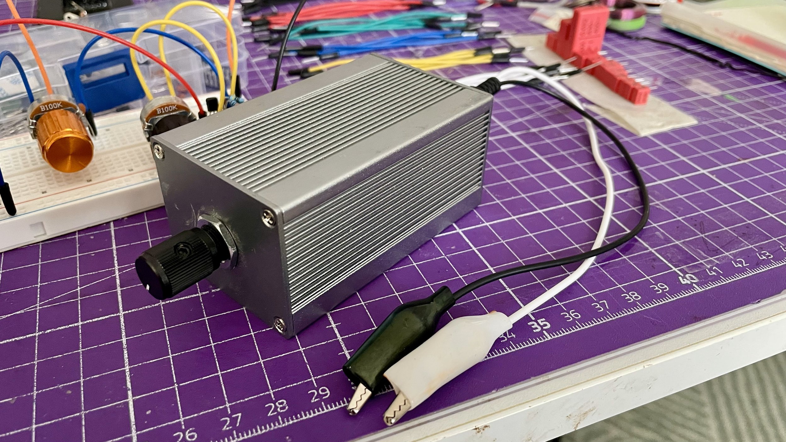
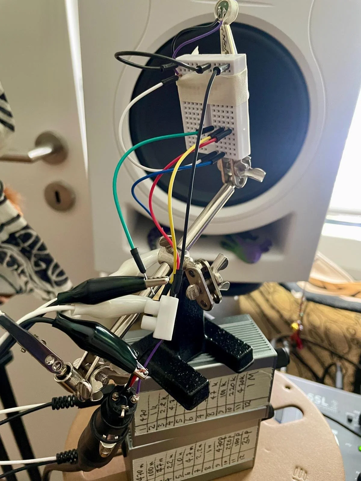
The component testers in action, fine-tuning the HPF and LPF of our DIY mic (EMR 5024)
The mini breadboard is FAR from pretty, but absolutely necessary, so I don’t have to desolder for every test. I would like to take a moment to thank crocodile clips and helping hands, too. 😂
The very top of the image, help up by a croc clip, is the mic capsule. It’s listening to white noise played back from the studio monitor. The only variable in these clips is the capacitor rating (33pF - 470nF).
The diagrams from the video:

HIGH pass filter

LOW pass filter
2025 07 12 Testing caps in-line
You shouldn’t do this. This is just a test for myself, to figure out which cap would work best for my purpose. I figured this test might help someone in the future, in case they need to do the same.
Signal path: Guitar - splice box in - capacitor tester - splice box out - interface+ampsim. I didn’t use amps/pedals for this because I didn’t want the internal high pass filtering in them to influence my test, since the first process many (most?) pedals or amps do is high pass filter the signal.